| CPU |
STM32L100RBT6 |
| Clock |
16 MHz |
| Operating voltage |
3.3 V |
Overview
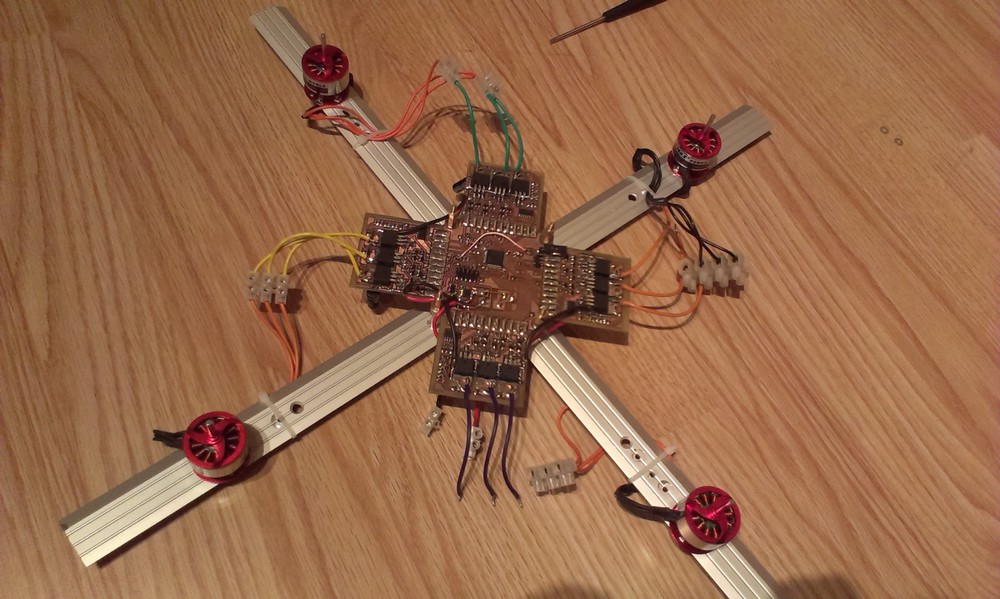
Main task of this device is to drive four motors in my quadcopter. The Quad Brushless DC driver consists of 5 parts - a controller module with microcontroller
and four power modules.
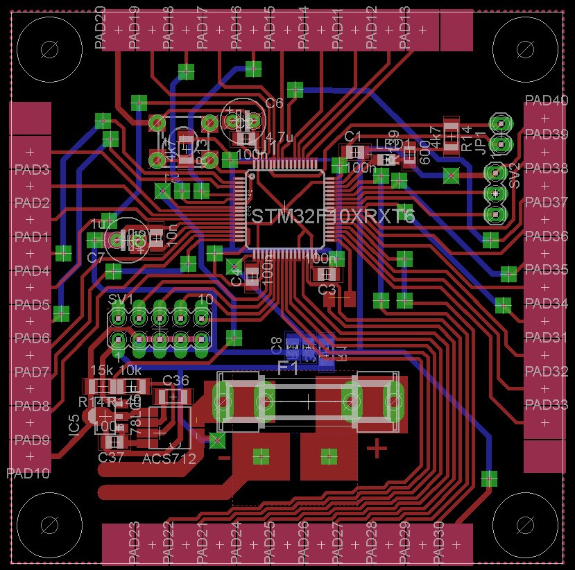
Controller module
Controller module is based on ARM microcontroller from ST - STM32L100RBT6. It is an ultra low-power µC running at 16MHz
with a lot of timers needed to drive 4 motors with Back-EMF sensing.
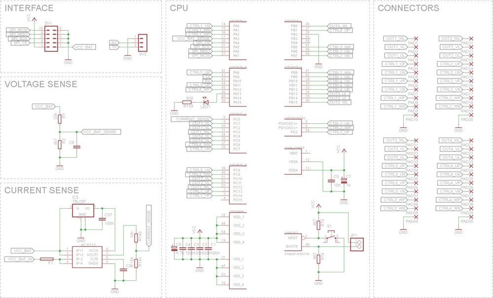
Resources usage
-
3 timers with 4 PWM outputs each - driving Low side MOSFETs of power modules.
-
12 control lines driving High side MOSFETs.
-
12 interrupts - each connected to proper comparators' outputs.
-
4 timers - providing timing during starting and normal running (with Back-EMF sensing) phases.
-
ADC - sensing bus voltage and current.
-
SPI - comminication with flight controller - receiving desired PWM duties and sending current motors' states and speeds (with DMA)
-
Only 6 pins of LQFP64 package are unused.
Thoughts
Cortex-M3 has an excellent feature, which is interrupt preemption. It allows to specify BLDC driving interrupts
to have the highest priority while communication interrups are left at lower. This makes that communication doesn't have
any influence on commutations.
There were a few limitations when it comes to pinout. Previously, I used STM32F1 series where Timer's PWM outputs can be
remapped only in full or half blocks. Moreover every interrupt has to be on its own pin number. For example,
if motor 1 BEMF interrups are connected to ports A1, D2, C3, then motor 2 interrupts
cannot be connected to pins like B1, C1, D1, A3, etc. Additionaly, some JTAG pins are pulled up on start and in bootloader mode
what causes opening MOSFETs and short circut as a result, so those pins are not used to control phases).
This introduced a very fixed pinout.
Software
This µC has to deal with huge amount of commutations every second (e.g. 7000 commutations per motor per second * 4 motors results in
28000 phase changes per second).
It ends up with about only 570 cycles available for each commutation event.
Every commutation consists of setting up new six phases, setting up external interrupts system
to wait for specific edge on comparator's output (Back-EMF sensing) as well as setting up delay timer to ommit phase change voltage spikes.
Regardless of commutations, the system has to manage starting phases,
supervise rotor speeds and take adequate actions in case of wrong motors' states, respond to communication with flight controller
and monitor bus voltage and current as well.
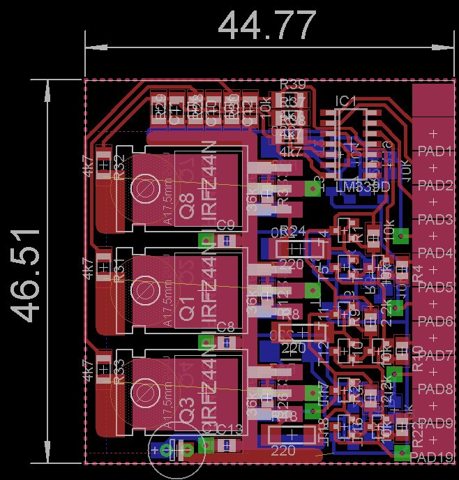
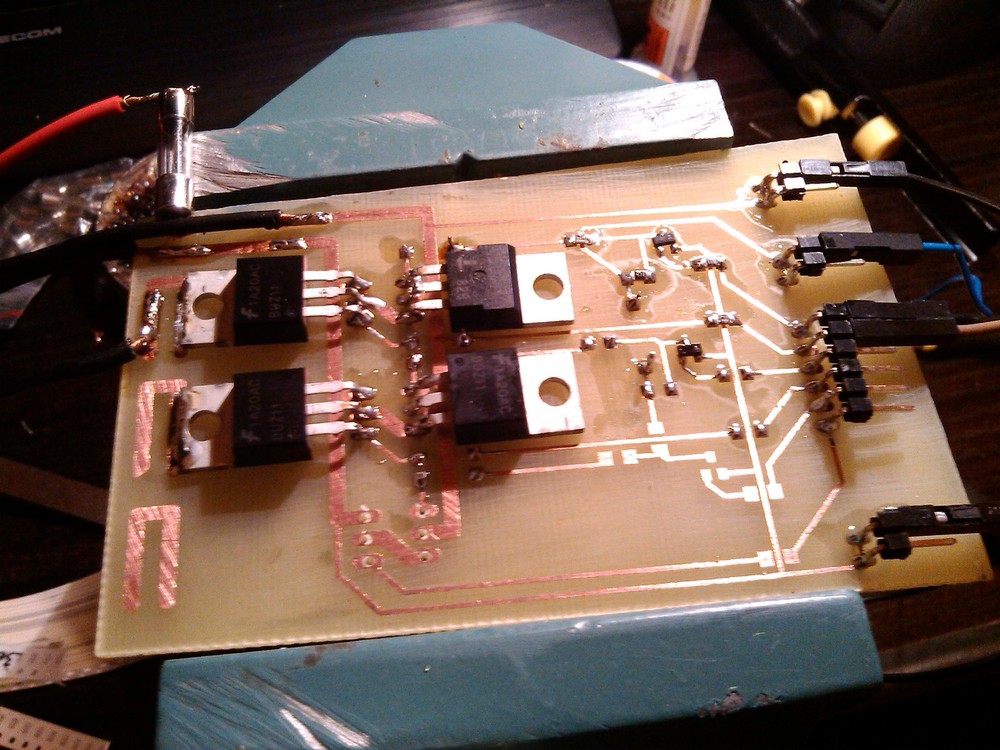
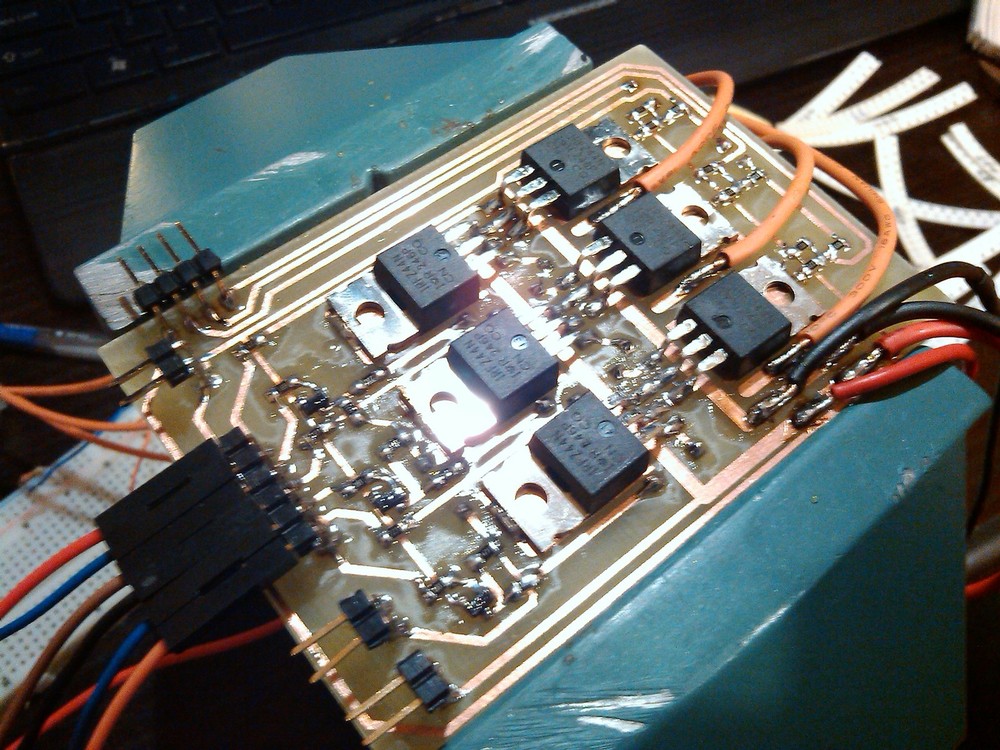
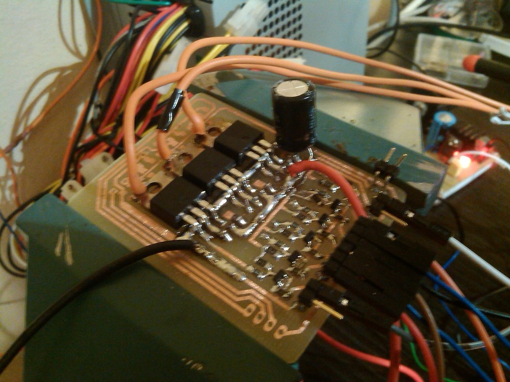
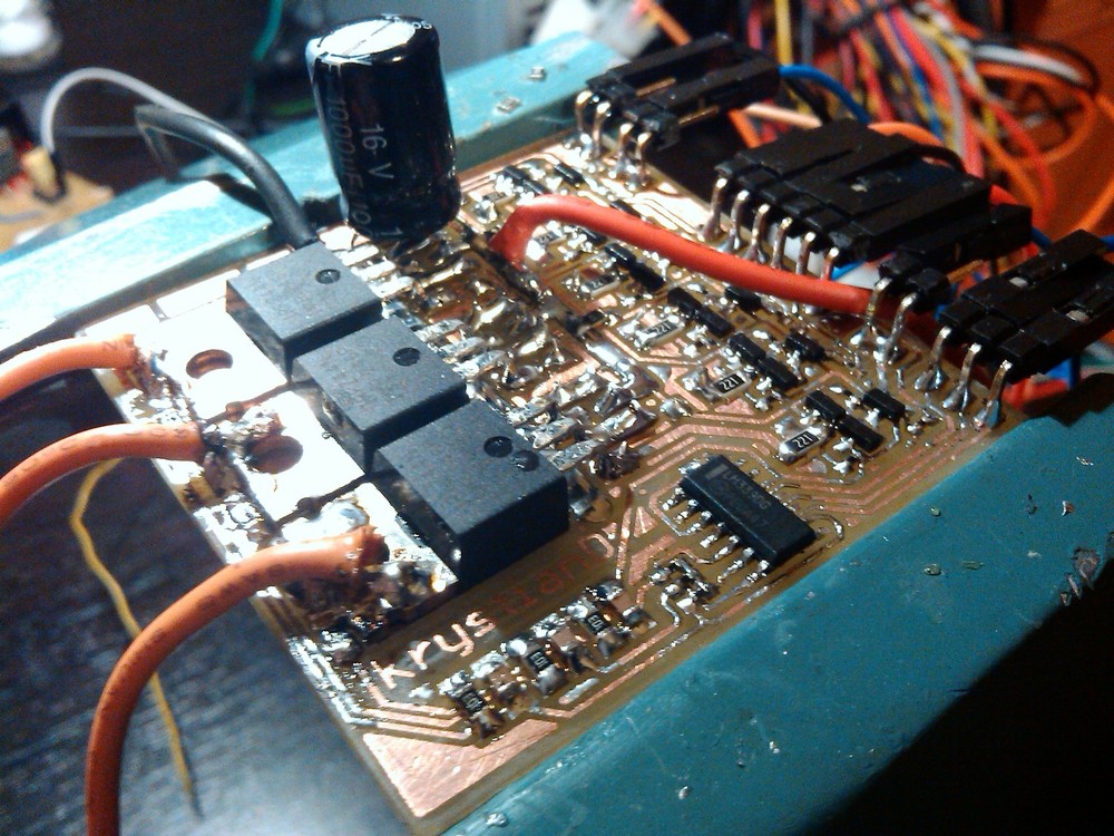
Power modules
Those are final versions of my BLDC drivers. Each module consists of 6 power MOSFETs, 18 transistors,
comparator chip and tons of resistors and capacitors.

|
|
One phase
|

|
|
Comparators
|

|
|
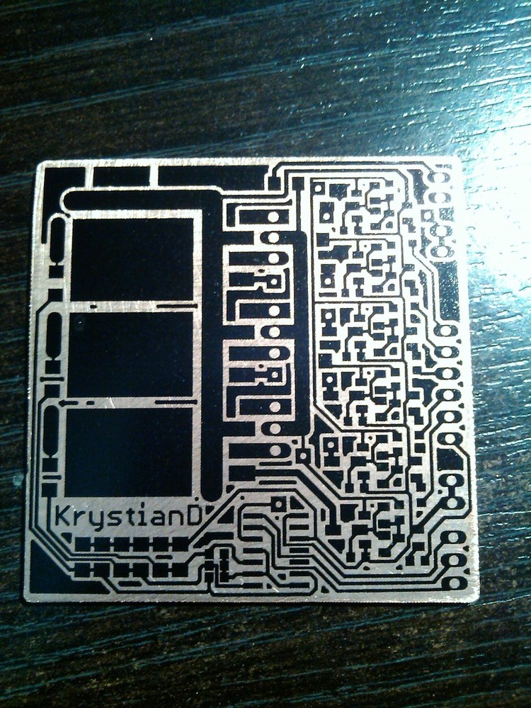
Driver board
|
|
|
High side
P-MOSFET
|
Low side
N-MOSFET
|
|
Part
|
IRF4905
|
IRFZ44N
|
|
On-resistance
|
20mΩ
|
17.5mΩ
|
|
Max current
|
-74A
|
49A
|
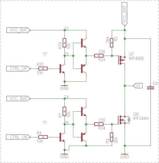
I use P-MOSFETs at high side instead of N-MOSFETS with charge pump because some tests have shown a lot power wasting in voltage converting to
higher values (18 V in this case), moreover, I found cheap low On-resistance P-MOSFETs.
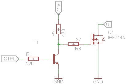
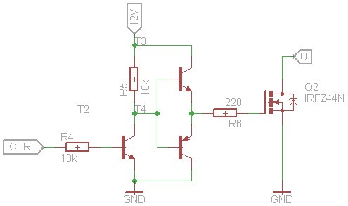
Every MOSFET is controlled by Push-Pull stage build with commonly used transistors. As a result, both charging and discharging of
MOSFET's gate are made through limiting resistor resulting in about 500mA (dis)charging peak current. There is
no leakage current in off state. It also allows to use low voltage controlling singals.
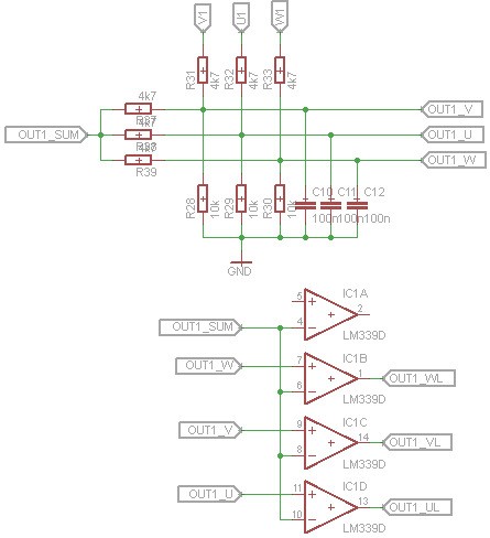
Back-EMF is compared with the sum of Back-EMF singals by LM339 quad comparator and exposed as open-collector outputs which are
connected directly to microcontroller.
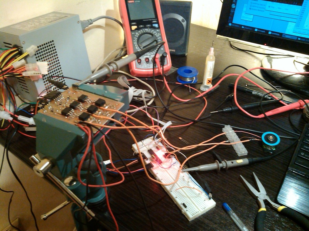
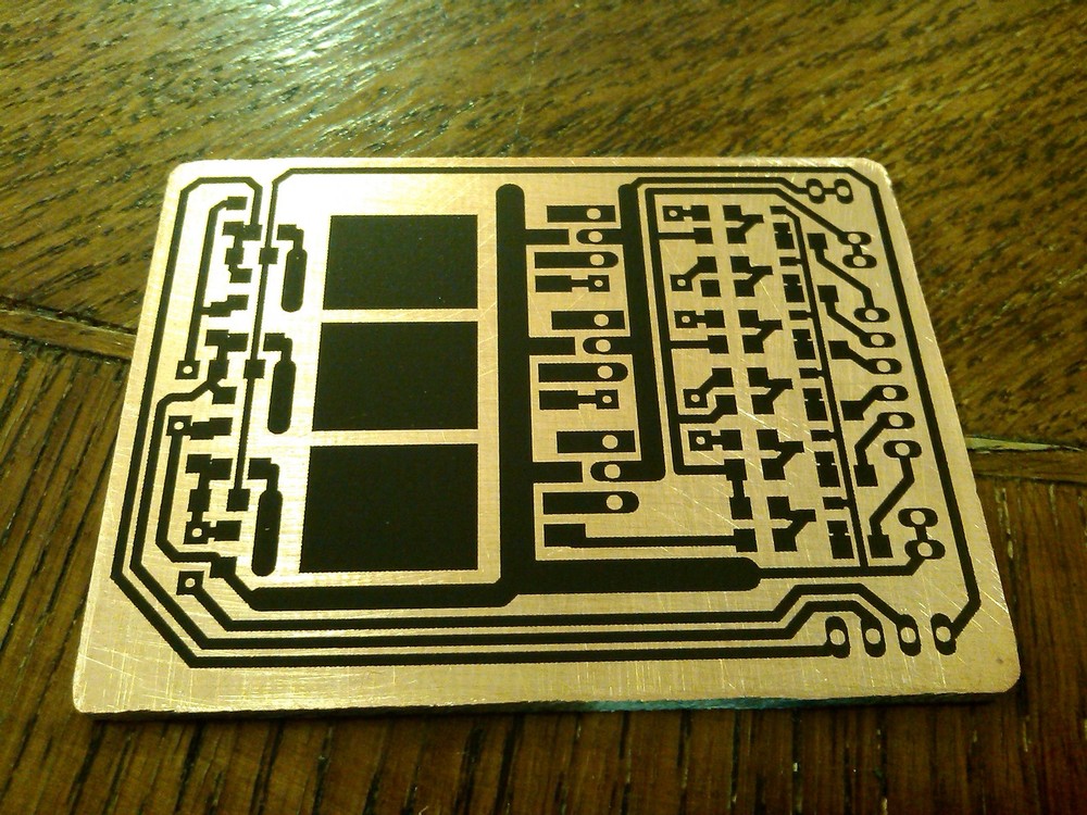
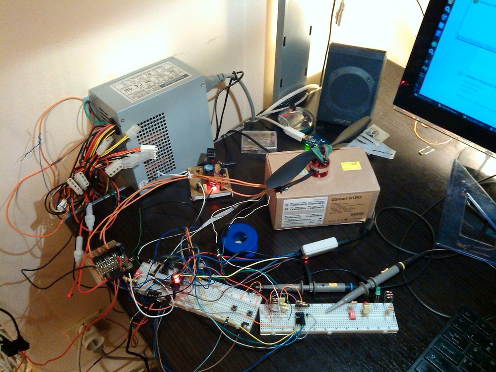
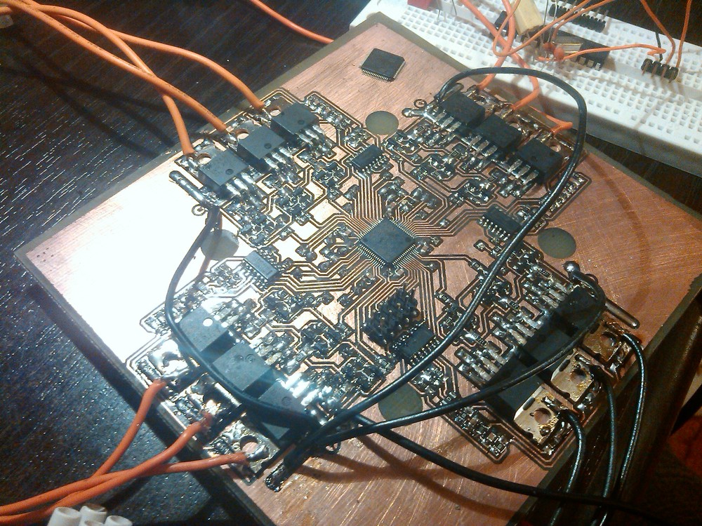
Photos & videos of development stage