| Start date |
February 2013 |
| Weight |
700g
with batteries |
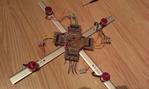
Short story
My goal was never to create a quadcopter, I always knew it is very difficult task, especially, because of the fact that
I like reinventing the wheel and do everything from scratch. At the beginning, I just wanted to make BLDC motor driver,
it worked, then, I
attached a propeller
and an accelerometer and tested if I was able to write a speed controller for a motor attached at the end of a long arm.
I was. The arm was reaching desired angles
very fast. Then I made a double driver and a simple quad frame,
attached them to it,
it worked,
the controller was able to keep the frame at "fixed" position. Then I made a
quad driver, a remote controller, tons of PCBs,
thousands lines of code, and it is, my own quadcopter.
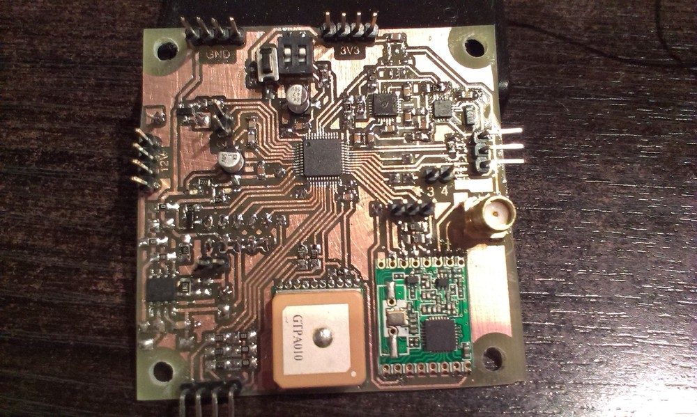
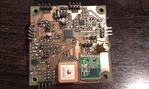
Flight controller
|
|
Flight controller
|
|
|
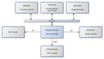
Flight controller diagram
|
| Microcontroller |
STM32F103C8T6
32-bit ARM Cortex-M3 |
| Clock |
8 MHz |
| Peripherals |
MPU6050
Accelerometer/gyroscope
HMC5883L
Magnetometer
BMP085
Pressure sensor
FGPMMOPA6E
GPS module
RFM69HW
Radio module (FSK)"
|
| Power supply |
MC34063
DC/DC converter from 12V to 3.3V |
Flight controller is the heart of the whole system. Its main task is to take care of processing accelerometer,
gyroscope and magnetometer sensors reads, computer current rotation quaternion, extract Roll-Pitch-Yaw information from it,
compute motor speeds (PWM duty) using Roll-Pitch PI controller and Yaw P controller and send this data to the motors driver board.
Other module tasks:
-
Supervise battery cells voltages
-
Process GPS data
-
Transmit and receive data to/from remote controller and PC interface
-
Process barometer reads
-
Manage critical situations like connection lost with remote controller
Motors driver
|
|
BLDC driver
|
| Microcontroller |
STM32L100RBT6
32-bit ARM Cortex-M3 |
| Clock |
16 MHz |
Instead of buying several regulators like
this, I decided to make my own, which is
described on separate page ->
BLDC driver
Main task of the driver is to drive four [alt="Brushless DC"]BLDC[/alt] motors with [alt="Pulse Width Modulation"]PWM[/alt]
duty factors obtained from flight controller.
Moreover, the module manages motor states. That is, when one motor stops due to mechanical reasons (e.g. hit something), driver
can restart it or stop other motors depending on the settings provided from flight controller. The module is also equipped with
current Hall-based sensor ACS712 which can measure current up to 25A in both directions.
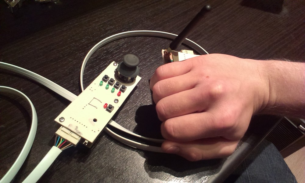
Remote controller
| Microcontroller |
STM32F103C8T6 x2
32-bit ARM Cortex-M3 |
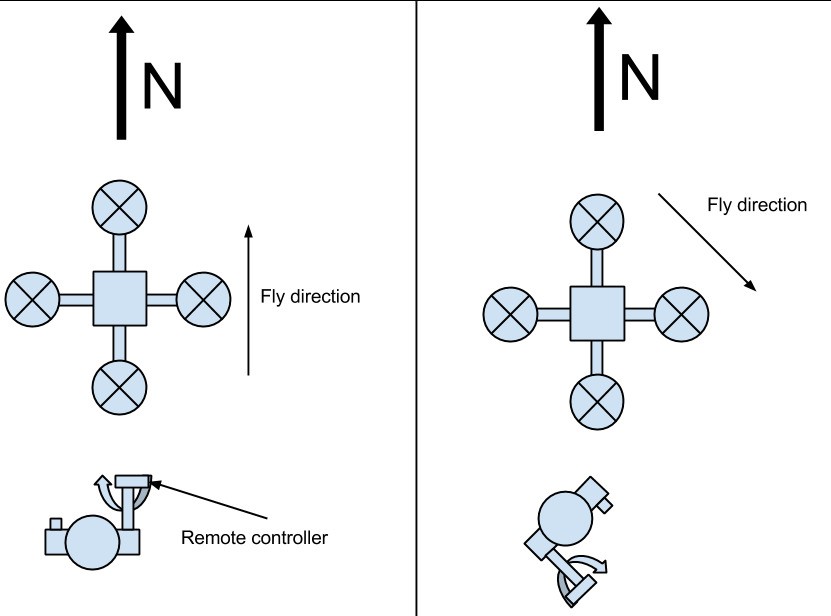
Whole flight control is done by proper rotating of one part of the remote controller. It is equipped with the same set of
sensors and algorithms as main flight controller board. Thanks to this, quadcopter can follow remote controller's movements.
Both systems know absolute and relative orientation of each other. It allows to easy controlling without taking care of quadcopter's frame
orientation. For example, if I turn remote controller right, the quadcopter will always fly right, even, if I turn myself around.
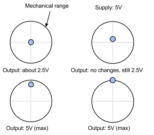
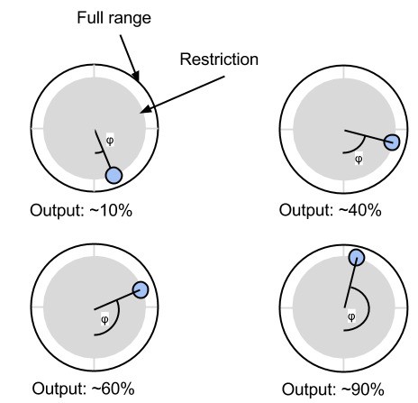
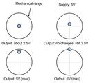
Second part of the remote controller controls throttle.
PS2 joysticks have very poor resolution, they start changing voltage
very late (after about 1-2mm) and get saturated very early.
|
|
Joystick problem
|
|
|
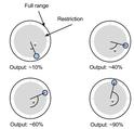
My solution
|
My solution is to take inclination angle of the knob instead of its absolute position and restrict mechanical movements to prevent
results of being saturated. It is simple arctan(y/x) in fact, but allowed me to still use those joysticks.
PC interface
Interface between remote controller, quadcopter and software on PC. KDcopter software on PC provides a lot information about
current state of the quadcopter like cells voltages, sensor reads, quadro and remote controller positions and lot of other
things.
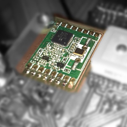
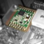
Radio communication
|
|
RFM69HW
|
| Frequency |
868 MHz |
| Tested range |
200 m |
Radio communication is done by RFM69HW modules. My own protocol includes simple collision detection algorithm and some kind of
time division algorithm. Every devices sends its data every 20ms. After transmission, the module is switched to Receive Mode and
starts to listening for a packet. If there is some packet being transmitted in the air, module receives it and postpones
transfer until packet is received. There is also some random time added after each reception to allow
recovery in case of collision and to allow other transmiter to switch to Receive Mode.
Control panel
-
GPS
Quadcopter, as well as remote controller are equipped with GPS receivers. They are not currently used to control position, but they work and
provide real location.
Resources
Gallery
See full gallery on Flickr