History
The first idea of the project was to control temperature on the central heater and signal whether the temperature goes above or below the threshold.
First saved date is on 2010-04-27 and that's the project implementation date. Since that time, project has been significantly extended:
-
Energy counter was connected and energy statistics were written (2011-05-25).
-
Water counter was created and connected (2011-07-26).
-
Battery voltage meter was built and connected to the main PC (2012-02-09).
-
Voltmeter was extended to be able to control discharging and charging process of the battery (2012-04-07).
System elements
-
Software
-
Daemon for reading temperatuer sensonrs. (C++, 1-Wire)
-
Daemon for updating database (C++)
-
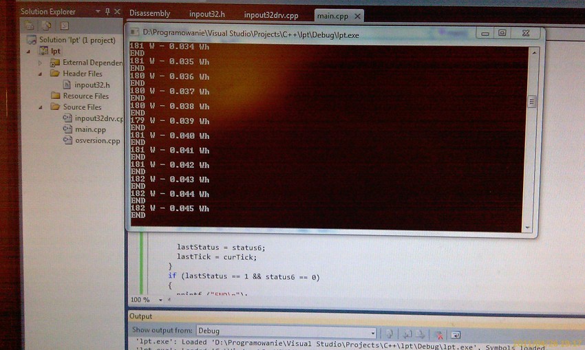
Daemon for reading energy and water couters pulses (C++)
-
Admin panel for reading data and statistics
-
Hardware
-
Linux-based PC (Ubuntu)
-
USB <-> sensors interface (dedicated hardware)
-
Voltmeted (dedicated hardware)
-
Temperature sensors (DS18B20)
-
PC speaker
-
Converter 1-Wire -> COM
-
Energy counter (OR-03Y)
-
Water counter
-
Water counter reader (dedicated hardware)
Elelemts description
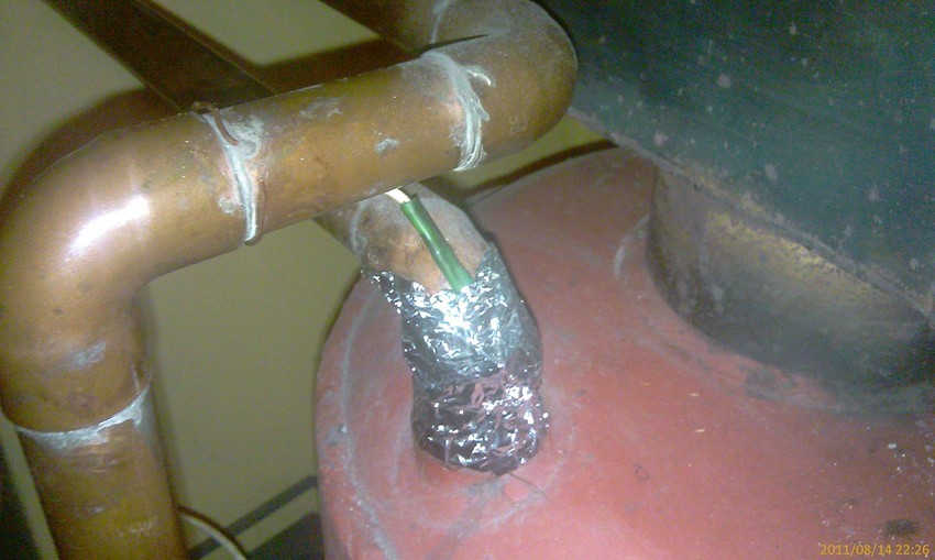
Temperature sensors
DS18B20 temperature sensors are attached to various water pipes and placed outside the house. The work in 1-Wire technology that allows to connect
multiple sensors to only 3 wires. They are connected to the main computer via 1-Wire -> COM converter and are managed via dedicated application.
Alarm states are signaled via PC speaker located in the living room.
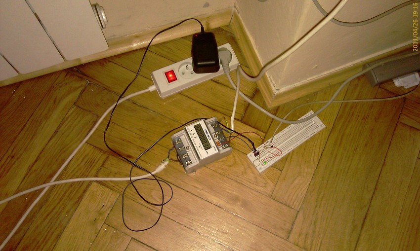
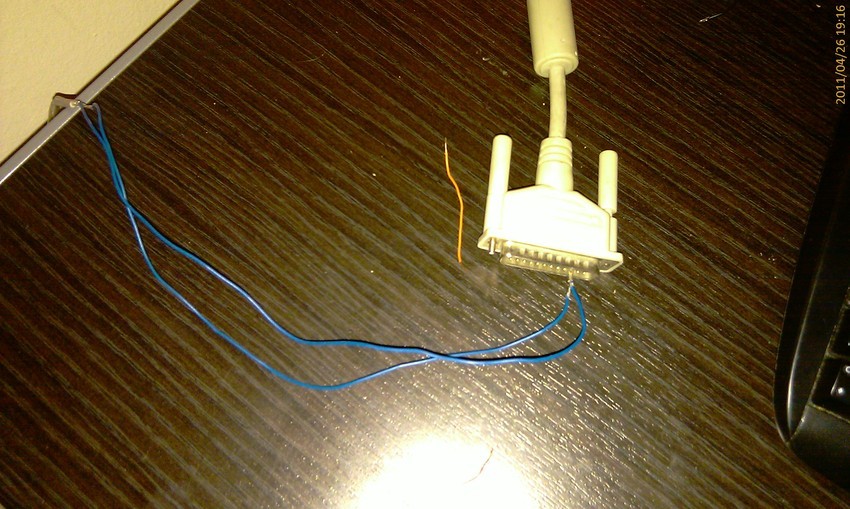
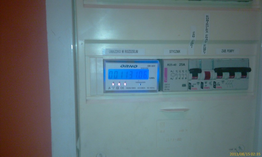
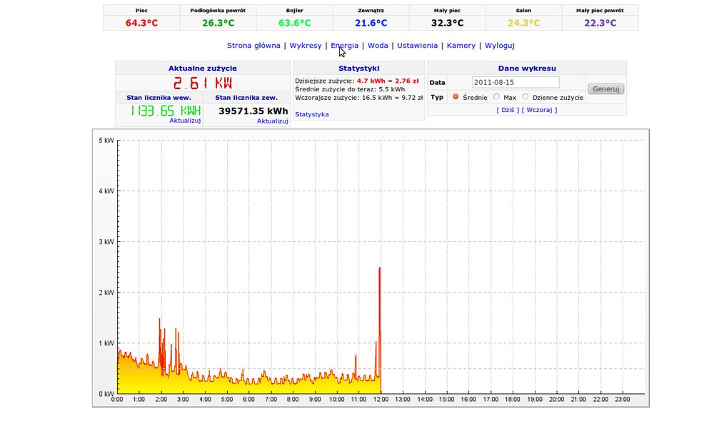
Energy counter
OR-03Y energy counter is located in the main electrical distribution unit just before the differential switch. That allows to measure whole energy consumed by house.
Pulse output is connected to USB interface. Every impulse signals 1 watthour. Time since last pulse allows to calculate instantaneous power consumption.
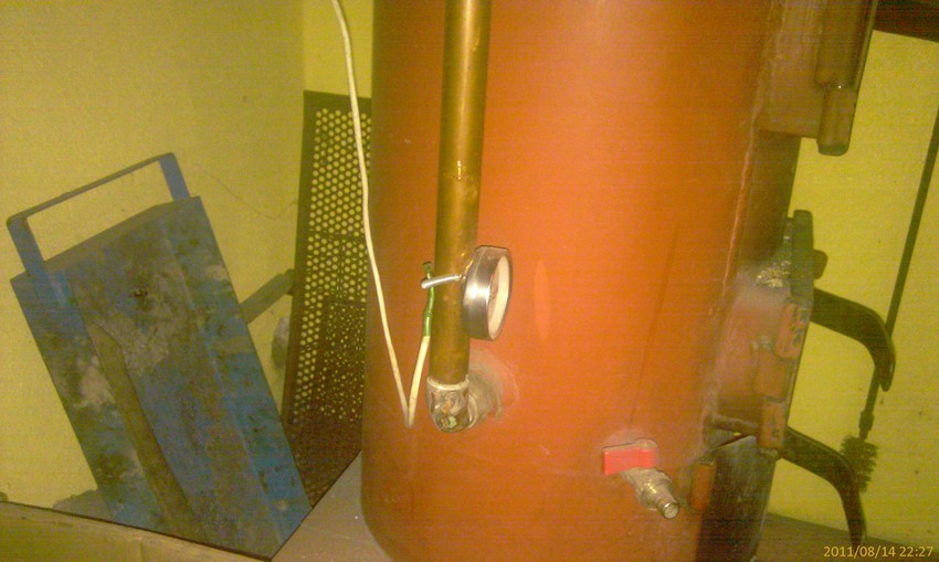
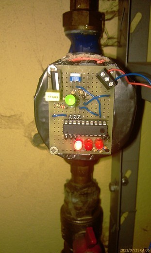
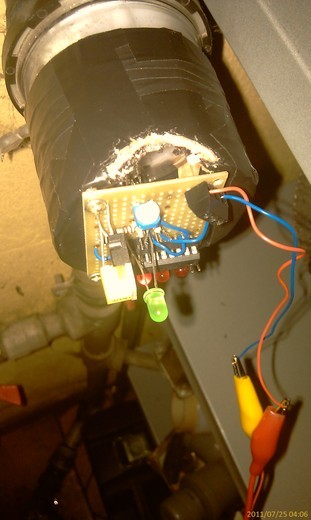
Water counter
Dedicated electronic cicruit that measure light reflected from rotating mirror in the water meter.
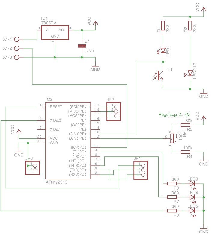
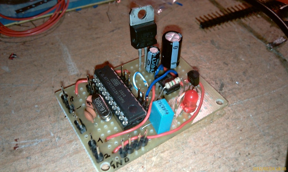
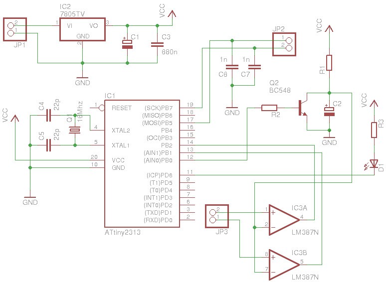
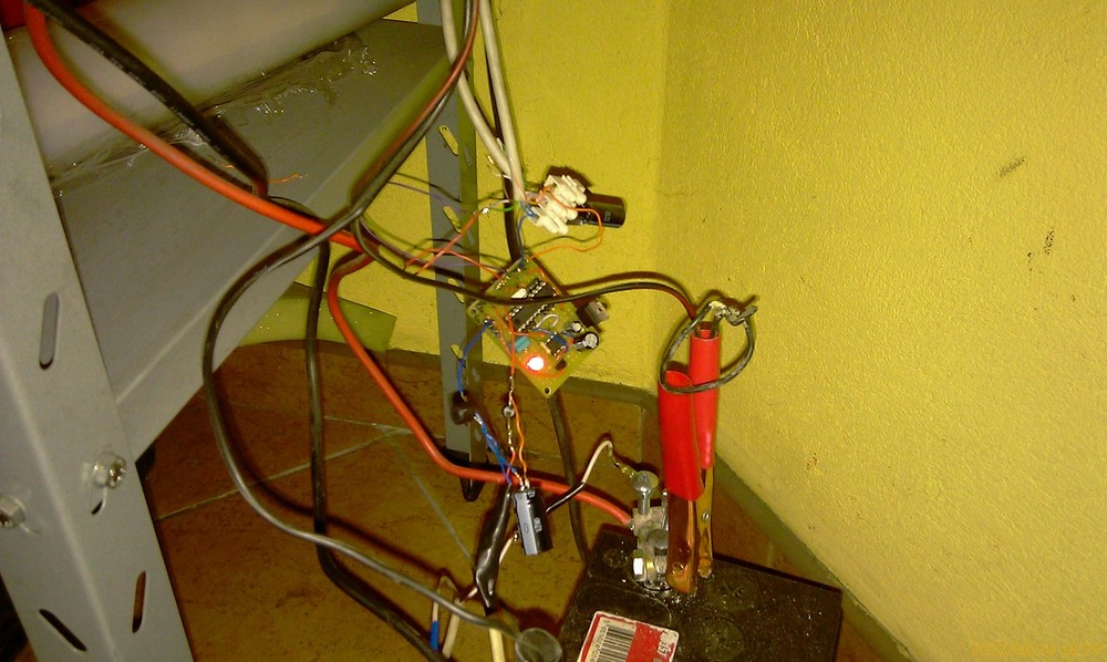
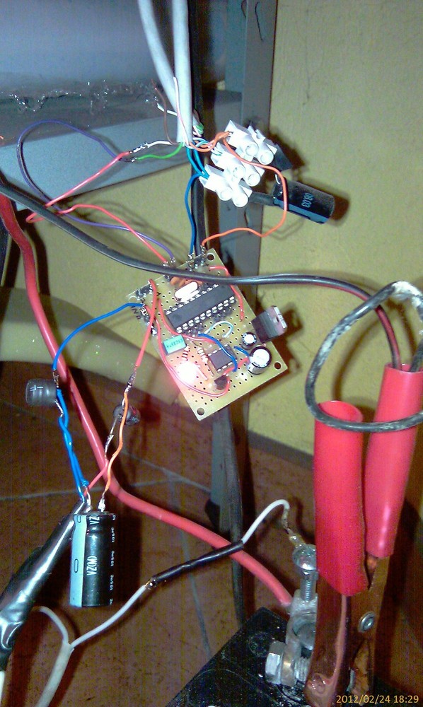
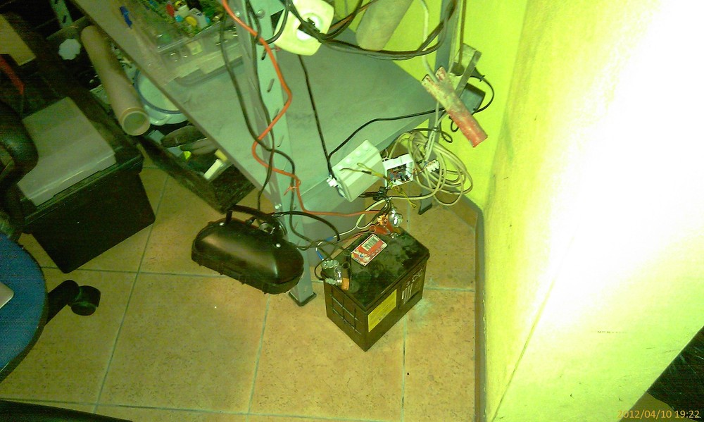
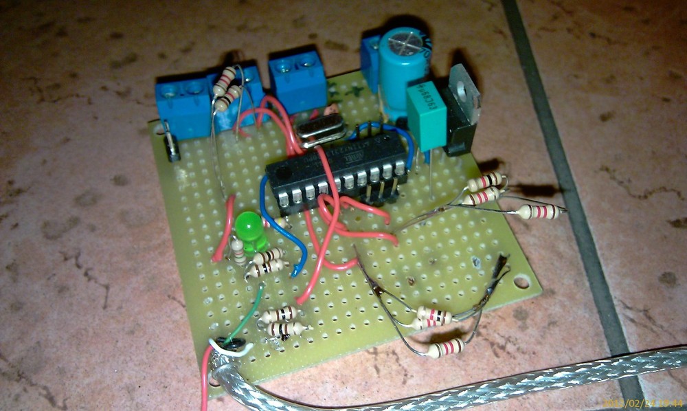
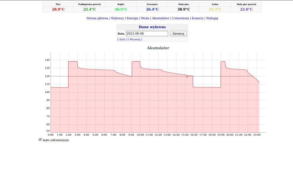
Voltmeter
Dedicated electronic cicruit that measure the voltage on backup power battery. I used ATtiny2313 microcontroller that communicates with PC interface via
I2C interface. There is a RC circuit on the PCB that allows to measure battery voltage (ATtiny2313 doesn't have an ADC).
The circuit also controls two relay switches connected to battery charger and lamp.
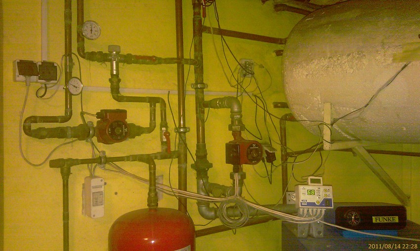
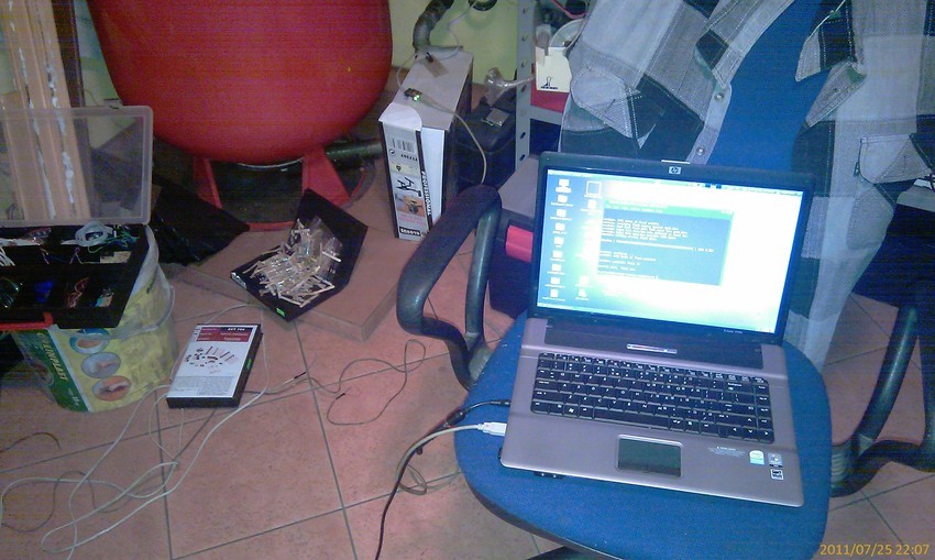
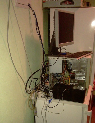
Computer
Heart of the system is Linux-based PC
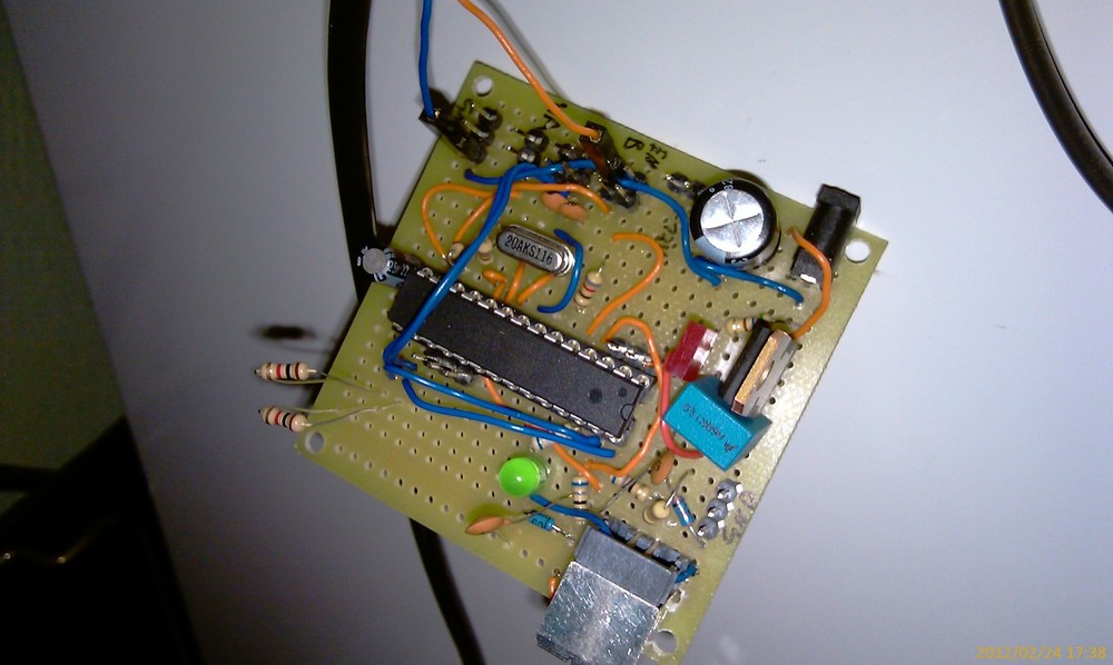
USB interface <-> sensors
This circuit allows computer to communicate with sensors. It is connected to PC via USB interface. It has 4 pulled up inputs and 2 lines for I2C interface.
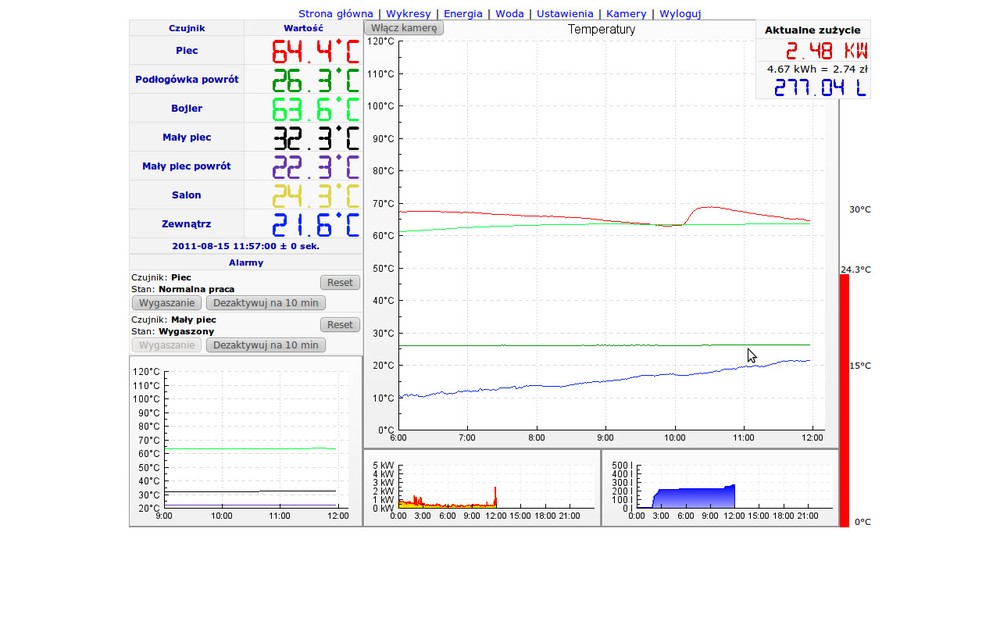
Control panel
All data and settings are available via WWW interface available through the Internet. On the main page there are most important information: temperatures,
alarm states, current energy and water usage. Other pages allow to browse and analyze historical data and graphs.